

---Español-------English


CONTROLLING PARALLEL PORT USING IO.DLL AND VISUAL BASIC
Goal: To develop a simple source code in Visual Basic 6.0 to control the parallel port using IO.DLL library sending it bytes. This application will run on WIN9x, WIN2000 and WINXP.
Utility: To Send data (bytes) to pins of parallel port which could result very useful to control loads such as relays or triacs as well it could serve to communicate with microprocessors or microcontrollers. Obviously we must use appropriate external circuitry for interfacing to them.
Utility: To Send data (bytes) to pins of parallel port which could result very useful to control loads such as relays or triacs as well it could serve to communicate with microprocessors or microcontrollers. Obviously we must use appropriate external circuitry for interfacing to them.
Background
Many desktops and some laptops have parallel ports. It can see in their several connector types. Usually the connector for parallel port is a DB-25 female whose color is generally purple. The pin distribution for parallel port is shown in figure 1.

Figure 1. Parallel Port Pin Distribution
The parallel port standard has three bytes as follows: DATAPORT, STATUSPORT and CONTROLPORT.
On this project we going to use DATAPORT, it means D0 up to D7 (PIN2 up to PIN9), to send data control word and PIN25 (GND) as electric reference.
The DATAPORT has an assigned address which may change from machine to machine.
In order to establish appropriate address of this port, you must go to control panel, system, hardware, device manager and ports(COM&LPT). Then you do right click on LPT1 or LPT2 according to your case, and left click on properties. After that, you must search Resources in the new window and look at range for your parallel port. To my case I see:
I/O Range 378-37F
Since this range is in hexadecimal we can convert it to decimal, therefore the range is:
I/0 Range 888-895
I select 888 as default.
Microsoft has recently created protection modes for ports doing difficult access to them. For this reason we need a library to access these parallel ports. This library is IO.DLL which you could download doing left click on blue link and then run it following these steps:
Software Development
1. You may create a New Standard.exe project on Visual Basic 6.0 (see figure 2).
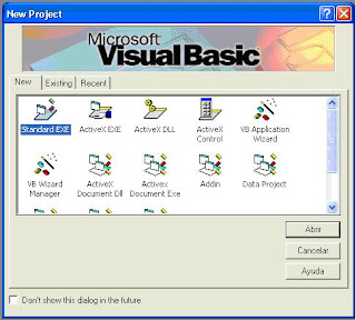
Figure 2. New Project Standard .exe
2. Add a Module using Add form tool (see figure 3).
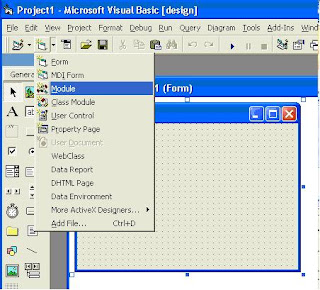
Figure 3. Adding General Module
3. Open New Module and paste this code:
Public Declare Sub PortOut Lib "IO.DLL" (ByVal Port As Integer, ByVal Data As Byte)
Public Declare Sub PortWordOut Lib "IO.DLL" (ByVal Port As Integer, ByVal Data As Integer)
Public Declare Sub PortDWordOut Lib "IO.DLL" (ByVal Port As Integer, ByVal Data As Long)
Public Declare Function PortIn Lib "IO.DLL" (ByVal Port As Integer) As Byte
Public Declare Function PortDWordIn Lib "IO.DLL" (ByVal Port As Integer) As Long
Public Declare Sub SetPortBit Lib "IO.DLL" (ByVal Port As Integer, ByVal Bit As Byte)
Public Declare Sub ClrPortBit Lib "IO.DLL" (ByVal Port As Integer, ByVal Bit As Byte)
Public Declare Sub NotPortBit Lib "IO.DLL" (ByVal Port As Integer, ByVal Bit As Byte)
Public Declare Function GetPortBit Lib "IO.DLL" (ByVal Port As Integer, ByVal Bit As Byte) As Boolean
Public Declare Function RightPortShift Lib "IO.DLL" (ByVal Port As Integer, ByVal Val As Boolean) As Boolean
Public Declare Function LeftPortShift Lib "IO.DLL" (ByVal Port As Integer, ByVal Val As Boolean) As Boolean
Public Declare Function IsDriverInstalled Lib "IO.DLL" () As Boolean
---4. Finally, on form1 add eight Command Buttons, one per each bit of DATAPORT. Also you can add two additional Command Buttons, one to clear DATAPORT and another to set all DATAPORT on ‘1’. An example for this form is shown in figure 4.
On this project we going to use DATAPORT, it means D0 up to D7 (PIN2 up to PIN9), to send data control word and PIN25 (GND) as electric reference.
The DATAPORT has an assigned address which may change from machine to machine.
In order to establish appropriate address of this port, you must go to control panel, system, hardware, device manager and ports(COM&LPT). Then you do right click on LPT1 or LPT2 according to your case, and left click on properties. After that, you must search Resources in the new window and look at range for your parallel port. To my case I see:
I/O Range 378-37F
Since this range is in hexadecimal we can convert it to decimal, therefore the range is:
I/0 Range 888-895
I select 888 as default.
Microsoft has recently created protection modes for ports doing difficult access to them. For this reason we need a library to access these parallel ports. This library is IO.DLL which you could download doing left click on blue link and then run it following these steps:
- Unzip the file to a new folder.
- Duplicate or cut the io.dll file and paste in C:\WINDOWS\system32.
Software Development
1. You may create a New Standard.exe project on Visual Basic 6.0 (see figure 2).
Figure 2. New Project Standard .exe

Figure 3. Adding General Module
3. Open New Module and paste this code:
Public Declare Sub PortOut Lib "IO.DLL" (ByVal Port As Integer, ByVal Data As Byte)
Public Declare Sub PortWordOut Lib "IO.DLL" (ByVal Port As Integer, ByVal Data As Integer)
Public Declare Sub PortDWordOut Lib "IO.DLL" (ByVal Port As Integer, ByVal Data As Long)
Public Declare Function PortIn Lib "IO.DLL" (ByVal Port As Integer) As Byte
Public Declare Function PortDWordIn Lib "IO.DLL" (ByVal Port As Integer) As Long
Public Declare Sub SetPortBit Lib "IO.DLL" (ByVal Port As Integer, ByVal Bit As Byte)
Public Declare Sub ClrPortBit Lib "IO.DLL" (ByVal Port As Integer, ByVal Bit As Byte)
Public Declare Sub NotPortBit Lib "IO.DLL" (ByVal Port As Integer, ByVal Bit As Byte)
Public Declare Function GetPortBit Lib "IO.DLL" (ByVal Port As Integer, ByVal Bit As Byte) As Boolean
Public Declare Function RightPortShift Lib "IO.DLL" (ByVal Port As Integer, ByVal Val As Boolean) As Boolean
Public Declare Function LeftPortShift Lib "IO.DLL" (ByVal Port As Integer, ByVal Val As Boolean) As Boolean
Public Declare Function IsDriverInstalled Lib "IO.DLL" () As Boolean
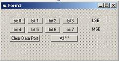
---4. Finally, on form1 add eight Command Buttons, one per each bit of DATAPORT. Also you can add two additional Command Buttons, one to clear DATAPORT and another to set all DATAPORT on ‘1’. An example for this form is shown in figure 4.

Figure 4. An example of main form.
5. The code for each Command Button of the figure 4 is:
Private Sub Command1_Click() ' bit 0 on 1
PortOut 888, 1
End Sub
Private Sub Command2_Click() ' bit 1 on 1
PortOut 888, 2
End Sub
Private Sub Command3_Click() ' bit 2 on 1
PortOut 888, 4
End Sub
Private Sub Command4_Click() ' bit 3 on 1
PortOut 888, 8
End Sub
Private Sub Command5_Click() ' bit 4 on 1
PortOut 888, 16
End Sub
Private Sub Command6_Click() ' bit 5 on 1
PortOut 888, 32
End Sub
Private Sub Command7_Click() ' bit 6 on 1
PortOut 888, 64
End Sub
Private Sub Command8_Click() ' bit 7 on 1
PortOut 888, 128
End Sub
Private Sub Command9_Click() ' D0 up to D7 off (0)
PortOut 888, 0
End Sub
Private Sub Command10_Click() 'D0 up to D7 on (1)
PortOut 888, 255
End Sub
Explanation
The PortOut Instruction has two parameters which are: port address and data word (byte). Both port address and data word must be in decimal format. In my case port address is 888. For this reason is very important that you identify port address number as previously it is explained. Once you have the new address port for DATAPORT you must change it into the code for each Command Button.
When you execute the previously software you could see that every time you click on each button one bit is set to ‘1’. To test this you may use a multimeter in voltage scale and its red test probe in the bit pin and its black test probe in pin 25. Also you may build a simple circuit using LEDs connected between the bit pin(anode) and GND(cathode).
NEW! You would see these circuits to complement this project or test this software.
Author's personal page here.
More tutorials, projects and news please visit:
Electrónica Plug and Play
No comments:
Post a Comment