Add to Technorati Favorites Electronics Projects and Articles: 2009

Friday, November 13, 2009

CIRCUITS FOR PARALLEL PORTS

I've created this blog to write electronics projects and electronics articles which can be used by any person interested in the electronic design. Your questions, doubts, comments and suggestions are welcome providing that they are written in a courteous and respectful way.

--Español-----English


CIRCUITS FOR PARALLEL PORTS
Previously on Projects category, I wrote the “Controlling Parallel Port Using IO.dll” article, but the circuits are still pending to use with this project which is dealt in this post.

Goal: Describing various circuits to use the parallel ports with the previous article “Controlling Parallel Port Using IO.dll” on "Projects" Category, giving external circuitry for interfacing with it.

Utility: Developing hardware to connect the parallel port appropriately to implement useful applications.

Circuits

Look at the following circuits:


The first circuit in figure 1, the Simple test circuit, is useful only to test the software. When a bit is set ‘1’ (you have clicked its button) you can see the respective LED turn on. You do not use external power supply for this circuit because the parallel port provides enough energy to turn on the led, TTL states, generally. In this way you can test every data pin on the parallel port of your machine.

The second circuit in figure 2 uses the ULN2803 which is an 8-bit 50V 500mA TTL-input NPN Darlington driver. The inputs on the left side of the IC (1-8 pins) are suitable to be connected directly to the PC parallel port output lines. The outputs are open collector outputs, so they are well suited for controlling various loads powered through external power supply. The load device can be as simple as a LED, a small motor, small light bulbs or a relay. In figure 2 you see the simple LEDs control using ULN2803 IC.
This Integrated Circuit also has diodes to protect it against reverse currents when loads such as motors and relays switch on and off. The line (pin 10) can, for example, be connected to the power supply line that supplies power to the relays. For example, You can also use 9V Zener diode connected to this line as a protection component which limits relay power supply to maximum less than 9V as in the figure 2. Or you can connect a 12V Zener diode from pin 10 to the relay power supply plus to limit spikes to power supply voltage plus 12V as in the figure 3. Do not use a power supply higher than 30V. In this circuit I control one relay but you can control up to 8 relays.
In any case you need an external power supply and coupling to the GND line of the PC with GND of the external power supply. These circuits can be useful to control dc loads up to 50 Vdc. The main idea in these circuits is to insulate external hardware control from internal circuitry in the parallel port and then to protect the parallel port.

If you want to control more power or mains voltage you can use the circuit in the figure 4.

Warning: When you are controlling mains voltage, you need to be very careful and must know what you do to do it safely. Mains voltage can injure you if you touch it, and a badly constructed circuit can overheat and cause a fire.

In figure 4 we can see that an opto-isolation is provided by the MOC3041 which is very safe for the PC. In addition, in figure 4 there is a TRIAC for switching the high dc voltage or mains voltage. In the example a 12A-600V Triac (Ref. BT138) is used but you must analyze the appropriate Triac according to your application.

Finally, all previous circuits can be also used with microcontrollers or microprocessors.

Author's personal page here.

More tutorials, projects and news please visit:
Electrónica Plug and Play

Thursday, May 7, 2009

Programmers for PICs

I've created this blog to write electronics projects and electronics articles which can be used by any person interested in the electronic design. Your questions, doubts, comments and suggestions are welcome providing that they are written in a courteous and respectful way.

--Español-----English


PROGRAMMERS FOR PICs

In a previous post on Firmware Category named "PIC Microcontrollers Languages", I described and compared the programming languages for PICs. However, a pending topic is the interface between the computer and the PIC micro. This article describes types of programmers but first I shall explain different development tools to contextualize the reader about the final goal: programmer.

Goals:

  • Clarifying concepts of terminology for development tools for PIC microcontrollers.
  • Understanding the basic concepts about programmer interface.
  • Describing the programmers of Microchip and giving other options for programming PIC microcontrollers.
  • A glance at Microchip’s Emulators and Debuggers tools.
Background
It is very important to explain some concepts for development tools of PIC microcontrollers. Sometimes, there is confusion among the words Compile, Debug, Simulate and Emulate. In electronic design these terms have different meanings.
Compile: It is the process of translating a source code to the language of the machine. Source Code in Assembly language or C language to OPCODES in Hexadecimal or Binary format.

Debug: It is the process to check the source code or program to eliminate possible mistakes from it and at the same time to optimize the program and increasing its velocity of execution. Debug processes are used in both design or development stages.

Simulate: In PIC microcontrollers, simulate is the way to carry out a real experiment into a virtual environment running the source code step by step or by loops to analyze the performance and affected registers in the device. You can even simulate logic states on the pins and check behaviors in your source code. You can do all of this if you have the appropriate software tools.

Emulate: When you have an appropriate interface you can pretend that you have a program memory PIC and run the source code (firmware) from a PC and look at program memory and file registers and at the same time look at the behavior of the source code when real external signals are applied.
We emulate to debug the source code. This emulation can be done in real time and to full speed (speed of PIC). All this not only requires an appropriate hardware interface but also the appropriate software to emulate from the PC.
Microchip classifies its development tools into four groups as follows:
  • Compilers: To compile source codes. In all cases these are software tools.
  • Emulators: To debug and emulate source codes, even to program devices.
  • Debuggers: To debug and develop, some of which also can provide services for programming.
  • Programmers: To program devices exclusively.

Figure 1. Microchip's Development tools classification.

Many development tools interact with the MPLAB Integrated Development Environment but not all need MPLAB IDE or a PC to work because some of them can work standalone mode for programming without a PC.

A programmer is an electronic device that communicates a computer and a PIC micro to transmit data, especially a compiled source code.

The interface block diagram is shown in figure 2.


Figure 2. Programmer interface diagram block.

Some debuggers and emulators can include a programmer interface or internal programmer device to program PIC microcontrollers.

A glance at Microchip's Emulators and Debuggers

In slide 1, I only describe general aspects about Microchip’s Development Tools, Emulators and Debuggers, but if you want to go into the subject in depth you can visit: START NOW WITH MICROCHIP DEVELOPMENT TOOLS page.


Slide 1. Microchip's Emulators and Debuggers.

Microchip's Programmers

The most popular Microchip programmers are detailed below:

1. MPLAB PM3

Definition: The MPLAB PM3 is a Universal Device Programmer which is easy to use and operates with a PC or as a stand-alone unit.


Uses:
  • Programming Microchip's entire line of PIC devices as well as the latest dsPIC DSC devices.
  • Program devices using ICSP. (In-Circuit Serial Programming.) on the target board.
  • Verify that code in the target microcontroller matches your firmware and verify that microcontrollers are blank.
  • Read code from an unprotected microcontroller into MPLAB IDE’s program memory window for debugging and programming into other devices.
  • With an optional MPLAB PM3 Card inserted, which is an SD-MMC memory card, you can store and transport device settings for programming.
  • Using MPLAB IDE as the interface, MPLAB PM3 becomes another tool in MPLAB IDE, allowing you to quickly compile, test and debug your firmware, then download it into MPLAB PM3 to be programmed into your device.
  • Without a PC connection to MPLAB PM3, the unit operates as a stand-alone device programmer. In this mode the main programmer features of MPLAB PM3 are available, including Read, Program and Verify.
Notes:
- Each version of MPLAB IDE has upgrades to support new devices in MPLAB PM3.
- A PC connection is required for operating system updates.
- MPLAB PM3 hardware requires the following software support if you are using a PC running Windows: MPLAB IDE software and USB communications driver.

Communications: MPLAB PM3 has two communication ports, Serial (COM 1-4) or USB (standard). Serial communications are 57.6K (default) or 9.6K baud, 8 data bits, 1 stop bit, no parity.

Components:
• MPLAB PM3 device programmer
• Serial Cable for RS-232 PC connection
• USB cable for USB PC connection
• ICSP cable
• Power supply and power cables
• MPLAB Integrated Development Environment CD
• User’s manual and technical documentation on CD
• Sockets to insert devices to program them.

Additional parts:
Main Sockets:
• Part Number: AC164301 - 18L/28L/40L DIP Socket Module for MPLAB PM3: This socket module supports 8P, 14P, 18P, 28P, and 40P DIP PICmicro or dsPIC devices on MPLAB PM3 Programmer.
• Part Number: AC164303 - 16L (.150), 18L, 28L (.300) SOIC Socket Module for MPLAB PM3: This socket module supports 64L TQFP PICmicro or dsPIC devices on MPLAB PM3 Programmer.
• Part Number: AC164305 - 44L TQFP Socket Module for MPLAB PM3: This socket module supports 44L TQFP PICmicro or dsPIC devices on MPLAB PM3 Programmer.
• Part Number: AC164306 - 20L TSSOP Socket Module for MPLAB PM3: This socket module supports 20L TSSOP PICmicro or dsPIC devices on MPLAB PM3 Programmer.
• Part Number: AC164307 - 28L SSOP Socket Module for MPLAB PM3: This socket module supports 28L SSOP PICmicro or dsPIC devices on MPLAB PM3 Programmer.
• Part Number: AC164308 - 68L PLCC Socket Module for MPLAB PM3: This socket module supports 68L PLCC PICmicro or dsPIC devices on MPLAB PM3 Programmer.
• Part Number: AC164309 - 44L PLCC Socket Module for MPLAB PM3: This socket module supports 44L PLCC PICmicro or dsPIC devices on MPLAB PM3 Programmer.

Cost: USD 895 Including all components except the sockets. The sockets have additional cost for sockets.

2. PICSTART PLUS

Definition: The PICSTART Plus is a Microchip microcontroller development programmer that enables you to program user software into PICmicro microcontroller devices.


Uses:
  • Using MPLAB IDE as the interface, PICSTART PLUS Programs PICmicro microcontrollers, including program memory, configuration bits and ID locations.
  • You can verify that PICmicro MCUs are blank, verify that code in the target microcontroller matches your firmware and you can read code from an unprotected PICmicro MCU into the MPLAB IDE program memory window for debugging and programming into other PICmicro MCU devices.

Notes:
- Devices in non-DIP packages that are supported by the PICSTART Plus require the use of an adapter. Those currently available are listed on the Microchip web site.
- In the future it is possible a firmware upgrade to include new devices. The firmware is upgradeable using MPLAB IDE

Communications: PICSTART Plus provides communications with the host PC via an RS-232 9-pin, D type connector. PICSTART Plus is Data Communication Equipment (DCE), and hardware handshaking is via Clear-To-Send (CTS) and Request-To-Send (RTS). The unit defaults to a 19.2K baud rate, 8 data bits, 1 stop bit, no parity, Hardware flow control, FIFO Buffers should be disabled.

Components:
• PICSTART Plus development programmer
• RS-232 Interface cable to connect to any standard PC serial port
• 9V power supply
• MPLAB IDE
• Blank chip for programming

Cost: USD 200, This kit contains the programmer, RS-232 serial cable, power supply, user guide, and a copy of MPLAB IDE on CD.

3. PRO MATE II
Definition: The full-featured, modular PRO MATE II device programmer lets you quickly and easily program your software into Microchip’s entire line of PIC MCUs, KEELOQ security products and Serial EEPROMs. PRO MATE II runs under MPLAB IDE and operates as a stand-alone unit or in conjunction with a PC-compatible host system.


Note: This product is no longer in production. It is still supported and accessories can be purchased for the immediate future.
OTHER SOLUTIONS
In addition to Microchip’s programmers there are several programmers that are offered by different manufacturers. Some of these programmers can support several devices and microcontrollers from other manufacturers and also Microchip devices including PIC microcontrollers. To name a few:

  • Conitec Data Systems has two device programming machines: GALEP-5 and GALEP-5D. Each one has its device list supported but Conitec has the free Device on Demand Service for fast implementation of a new chip into the programmer device list.
  • Xeltek has eight SuperPro Universal Programmers: 5000, 5004GP, 501S, 500P, 300U, 9000U, 280U, 580U. Some of them are stand-alone units. Also, whether you have a need for development or volume production purposes some of them allow you program more than one PIC micro simultaneously. Xeltek offers you free software updates available for download at its PIC Programmer software Download Center.
In addition to previously description about programmers, I can tell you that most of PIC Microcontrollers have an In-Circuit Serial Programming (ICSP) incorporated to them. This is important because in this way you can program a specific device. ICSP is an enhanced ISP (In System Programming) technique implemented in Microchip’s PICmicro One-Time-Programmable (OTP) and FLASH RISC microcontrollers (MCU) where a programmable device is programmed both before and after the device is placed in a circuit board. This technique use of only two I/O pins to serially input and output data makes ICSP easy to use and less intrusive on the normal operation of the MCU. Each Datasheet device provides its own specifications to implement ICSP. Remember, ICSP is only useful for a specific PIC micro therefore that ICSP circuitry couldn’t work appropriately for another reference. Additionally you need special software to load the OP CODES into PIC micro.

Finally, If you like do it yourself, on Internet you can find many options to build your own PIC programmer. There, you can find from specific device programmers up to Semi-Professional programmers, each one with its advantages and disadvantages. Also, it is possible that you need additional software to MPLAB IDE to burn a PIC with your firmware. I do not recommend any specific programmer because it depends on your requirements and I would have to build it and test it to recommend it to you.

Author's personal page here.

More tutorials, projects and news please visit:
Electrónica Plug and Play


Monday, April 6, 2009

PIC MICROCONTROLLERS LANGUAGES

I've created this blog to write electronics projects and electronics articles which can be used by any person interested in the electronic design. Your questions, doubts, comments and suggestions are welcome providing that they are written in a courteous and respectful way.

--Español-----English


PIC MICROCONTROLLERS LANGUAGES

Recently I have met many students and colleagues that ask me about how to program PIC microcontrollers. For this reason I have decided to write this article. In the present article you can find hints and tips to help you begin to program PIC microcontrollers.

Goals:

  • Clarifying concepts in programming languages for PIC microcontrollers.
  • Comparing the current programming languages for PIC microcontrollers and establishing their advantages and disadvantages.
  • Doing simple examples of the most important programming languages.
  • Knowing several compiler provider companies.
  • Drawing conclusions and to define the best language for programming PIC microcontrollers in a professional way.

Background

Commonly for many people the first obstacle to programming PICs is the language.
Actually when we program a PIC we do not use a specific language. We do not see when program is loaded into a PIC but when the PIC is loaded with our program the instructions are converted in OPCODES. The OPCODES are in a hexadecimal base. The type of PIC (low range, mid range or upper range) that you are programming always loads OPCODES.

For instance, the 286C it is an OPCODE for PIC microcontroller and the mnemonic for this OPCODE is GOTO 0X6C, that means go to the 6C program memory position.
When a program is compiled in a suitable compiler, no matter which language is used, it always generates an OPCODES list that has a file extension .hex.
If we create a TURNONLED routine, when we compile it a TURNONLED.hex will be generated and it will be the file that we will sent to PIC microcontroller.
In order to carry out the TURNONLED.hex file loading task we need to have an interface tool between the computer and the PIC microcontroller. This interface tool is called a programmer. We could talk about this subject on another occasion.

PIC Microcontrollers Languages

Among the several languages to program routines and subroutines I would like to mention the following:

- BASIC language
- C language
- Assembly language

You must please not confuse neither BASIC language or C language for PICs with Visual Basic, Visual C++ or similar IDEs because you can never program PIC routines using Object-Oriented Programming (OOP). We always use the instructions and structures of these languages with special editors and compilers for PIC microcontrollers.

The advantages, disadvantages, versions and examples for each language is detailed below.

1. BASIC Language

Advantages:

  • It is a simple language with easy reading instructions.

Disadvantages:

  • You will never have the control of the program. That means, You will never know either the time of instructions nor the running time.
  • There are difficulties when you want to use interrupts.
  • When the *.hex file is generated, it is not optimized, therefore you do not know the size of program memory used.
  • Most compilers for this language use windows environment.

Versions:

There are several companies producing BASIC language compilers and editors, among them I would like to mention:

www.letbasic.com
www.melabs.com
www.basicmicro.com

The most popular and which I think is the best is PICBASIC PRO by MicroEngineering Labs Inc. It is not free.

Example: This routine makes blinking a LED on port B 0 every 200 milliseconds. I use BASIC language designed in PICBASIC PRO.

2. C Language

Advantages:

  • This language is closer to machine language. Therefore, you can merge it with assembly language.
  • You can build math routines easily.
  • You can create macros to simplify your program.
  • Is accepted by Microchip, even it has some compilers to C language.

Disadvantages:

  • When the programs are compiled they can become somewhat extensive, so You must consider the program memory capacity. I recommend using this language with upper range PICs.

Versions:

Among the several companies that produce compilers and editor for C language for PICs I would like to mention:

www.microchip.com. It has C18 compiler for upper range and C30 compiler for dsPIC. Both C18 and C30 compilers can include them with MPLAB IDE. They are not free.
www.ccsinfo.com It has PCW IDE, PCWH IDE and PCWHD IDE. Each one offers the possibility to select the range to work and to compile for both Windows and Linux environments. The PCWHD IDE has all ranges for PIC microcontrollers and dsPIC. Besides it has a debbuger and Wizard that can generates a lot of source codes to initialize the program. You have a lot of libraries and you can integrate it with MPLAB IDE as well. These editors/compilers are not free.
www.htsoft.com (HI-TECH) it has PICC and PICC18 software tools. They are not free.

Example: This routine makes blinking a LED on port B 0 every 200 milliseconds. I use C language designed in CCS PCW IDE.


3. Assembly Language

Advantages:

  • It is the natural language for PIC in all ranges.
  • You have a total control of the program. You can take into account the instruction times and control all registers bit to bit.
  • You can build macros to simplify the source code.
  • There are no problem to handle simultaneous interrupts.
  • When the compiler generates the *.hex file it is entirely optimized.

Disadvantages:

  • I consider that this language does not have disadvantages, except when someone does not have experience in programming, this language could delay his developments.

Versions:

PIC microcontrollers have the MPLAB IDE editor/compiler/simulator which is completely free on www.microchip.com. This compiler is usually updated with new versions, but it works on Windows environment.
For Linux there is an alternative version named PIKLAB.

Example: This routine makes blinking a LED on port B 0 every 200 milliseconds. I use Assembly language designed in MPLAB IDE.


-->
Conclusions
Above, we saw the several options for programming PICs. I consider that If you want to program PICS in a professional way you can take into account the following advice:

1. It is ideal completely to know the Assembly language because you can take complete control of the program and all resources of the device. You also can build macros easily with it.

2. If you are going to begin to program PICs, you should begin with Assembly language. My advice is that you are not going to begin with BASIC language.

3. The C language is very useful for upper range (18xxxx family) and dsPICs, but this language can result very useful for other ranges if you combine it with assembly language.

Author's personal page here.

More tutorials, projects and news please visit:
Electrónica Plug and Play

Wednesday, March 25, 2009

Controlling Parallel Port with IO.dll

I've created this blog to write electronics projects and electronics articles which can be used by any person interested in the electronic design. Your questions, doubts, comments and suggestions are welcome providing that they are written in a courteous and respectful way.

---Español-------English


CONTROLLING PARALLEL PORT USING IO.DLL AND VISUAL BASIC


Goal: To develop a simple source code in Visual Basic 6.0 to control the parallel port using IO.DLL library sending it bytes. This application will run on WIN9x, WIN2000 and WINXP.

Utility: To Send data (bytes) to pins of parallel port which could result very useful to control loads such as relays or triacs as well it could serve to communicate with microprocessors or microcontrollers. Obviously we must use appropriate external circuitry for interfacing to them.

Background

Many desktops and some laptops have parallel ports. It can see in their several connector types. Usually the connector for parallel port is a DB-25 female whose color is generally purple. The pin distribution for parallel port is shown in figure 1.


Figure 1. Parallel Port Pin Distribution

The parallel port standard has three bytes as follows: DATAPORT, STATUSPORT and CONTROLPORT.

On this project we going to use DATAPORT, it means D0 up to D7 (PIN2 up to PIN9), to send data control word and PIN25 (GND) as electric reference.

The DATAPORT has an assigned address which may change from machine to machine.
In order to establish appropriate address of this port, you must go to control panel, system, hardware, device manager and ports(COM&LPT). Then you do right click on LPT1 or LPT2 according to your case, and left click on properties. After that, you must search Resources in the new window and look at range for your parallel port. To my case I see:

I/O Range 378-37F

Since this range is in hexadecimal we can convert it to decimal, therefore the range is:
I/0 Range 888-895

I select 888 as default.

Microsoft has recently created protection modes for ports doing difficult access to them. For this reason we need a library to access these parallel ports. This library is IO.DLL which you could download doing left click on blue link and then run it following these steps:
  1. Unzip the file to a new folder.
  2. Duplicate or cut the io.dll file and paste in C:\WINDOWS\system32.
Warning : you must beware of handling Windows and system32 folders because you could provoke malfunction in your OS.

Software Development

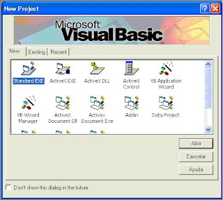
1. You may create a New Standard.exe project on Visual Basic 6.0 (see figure 2).


Figure 2. New Project Standard .exe

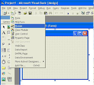
2. Add a Module using Add form tool (see figure 3).


Figure 3. Adding General Module

3. Open New Module and paste this code:
Public Declare Sub PortOut Lib "IO.DLL" (ByVal Port As Integer, ByVal Data As Byte)
Public Declare Sub PortWordOut Lib "IO.DLL" (ByVal Port As Integer, ByVal Data As Integer)
Public Declare Sub PortDWordOut Lib "IO.DLL" (ByVal Port As Integer, ByVal Data As Long)
Public Declare Function PortIn Lib "IO.DLL" (ByVal Port As Integer) As Byte
Public Declare Function PortDWordIn Lib "IO.DLL" (ByVal Port As Integer) As Long
Public Declare Sub SetPortBit Lib "IO.DLL" (ByVal Port As Integer, ByVal Bit As Byte)
Public Declare Sub ClrPortBit Lib "IO.DLL" (ByVal Port As Integer, ByVal Bit As Byte)
Public Declare Sub NotPortBit Lib "IO.DLL" (ByVal Port As Integer, ByVal Bit As Byte)
Public Declare Function GetPortBit Lib "IO.DLL" (ByVal Port As Integer, ByVal Bit As Byte) As Boolean
Public Declare Function RightPortShift Lib "IO.DLL" (ByVal Port As Integer, ByVal Val As Boolean) As Boolean
Public Declare Function LeftPortShift Lib "IO.DLL" (ByVal Port As Integer, ByVal Val As Boolean) As Boolean
Public Declare Function IsDriverInstalled Lib "IO.DLL" () As Boolean


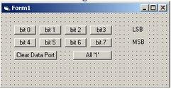
---4. Finally, on form1 add eight Command Buttons, one per each bit of DATAPORT. Also you can add two additional Command Buttons, one to clear DATAPORT and another to set all DATAPORT on ‘1’. An example for this form is shown in figure 4.


Figure 4. An example of main form.

5. The code for each Command Button of the figure 4 is:

Private Sub Command1_Click() ' bit 0 on 1
PortOut 888, 1
End Sub

Private Sub Command2_Click()
' bit 1 on 1
PortOut 888, 2
End Sub

Private Sub Command3_Click()
' bit 2 on 1
PortOut 888, 4
End Sub

Private Sub Command4_Click()
' bit 3 on 1
PortOut 888, 8
End Sub

Private Sub Command5_Click()
' bit 4 on 1
PortOut 888, 16
End Sub

Private Sub Command6_Click()
' bit 5 on 1
PortOut 888, 32
End Sub

Private Sub Command7_Click()
' bit 6 on 1
PortOut 888, 64
End Sub

Private Sub Command8_Click()
' bit 7 on 1
PortOut 888, 128
End Sub

Private Sub Command9_Click()
' D0 up to D7 off (0)
PortOut 888, 0
End Sub

Private Sub
Command10_Click() 'D0 up to D7 on (1)
PortOut 888, 255
End Sub


Explanation

The PortOut Instruction has two parameters which are: port address and data word (byte). Both port address and data word must be in decimal format. In my case port address is 888. For this reason is very important that you identify port address number as previously it is explained. Once you have the new address port for DATAPORT you must change it into the code for each Command Button.

When you execute the previously software you could see that every time you click on each button one bit is set to ‘1’. To test this you may use a multimeter in voltage scale and its red test probe in the bit pin and its black test probe in pin 25. Also you may build a simple circuit using LEDs connected between the bit pin(anode) and GND(cathode).

NEW! You would see these circuits to complement this project or test this software.

Author's personal page here.

More tutorials, projects and news please visit:
Electrónica Plug and Play